
Calculate and Examine Rendered Model
At this point let’s calculate the results.
- Make sure AGi32 is set to Full Radiosity Method (Calculate menu).
- Click on Calculate.
- Access the different viewpoints or pan around the drawing to inspect the calculated values. You can see your statistics for the various spaces in the Calculation Summary on the right side of the screen.
Let’s look at the rendered model. Visualization (rendering) serves several purposes: it’s an easy way to confirm you have placed the luminaires at the correct mounting heights (did you make any mistakes?), it is also a confirmation that you have created geometry properly (Rooms, Objects), then finally, it is a superb tool to evaluate the lighted environment (which we will explore).
- Click on the Render tab.
- Click on the Front View button.

Immediately you can evaluate many of the luminaire heights. It is also obvious where the wall color is different and carpet texture applied to the floor.
- Use the Orbit command to look around (orbit around the model).

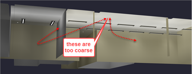
- Zoom in using the mouse wheel and then Orbit so you can see the ceiling in the open office area and the wall of the hallway (like below).
- Look closely at the patterns of light on those surfaces (below). They look rough or coarse.
- Turn on the radiosity mesh using the Wire Overlay button on the bottom of the rendered view.
- Click on the Clip (scissors, two left of Orbit) icon and hold down the left mouse button while moving into the view. Eventually, the front wall mesh will disappear as you are “clipping” the view.
Notice the division of the surfaces into polygons (mostly squares) is relatively coarse. This is fine for calculating illuminance on a workplane or floor, but is not sufficient to see accurate luminance gradients on the ceiling and walls.
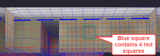
As an elementary radiosity lesson, in the image above you will see an area of the wall where a blue rectangle contains four red rectangles.
Red rectangles are Elements or receivers of light.
Blue rectangles are Patches or emitters of light.
When the calculation process begins, Elements accumulate direct light from the luminaires. Once the first pass has occurred with all direct light shot from the luminaires, the calculation process looks for the brightest patch and determines the amount of light not absorbed (based on surface reflectance). That reflected light is re-emitted back into the environment from the center of the Patch (think of it as a virtual luminaire). This continues from the brightest patch each step until eventually all the light is absorbed (you will notice AGi32 report % of light absorbed as the calculation process progresses), the point at which 100% of the light is absorbed is called Convergence.

